I often search for something unique to build. One unusual-looking airplane is Curtiss-Wright XP-55 Ascender. I contemplated building a scale model of the XP-55, but then I saw pictures of the Curtiss Wright CW-24B. It is similar to the XP-55 but has fixed landing gear.
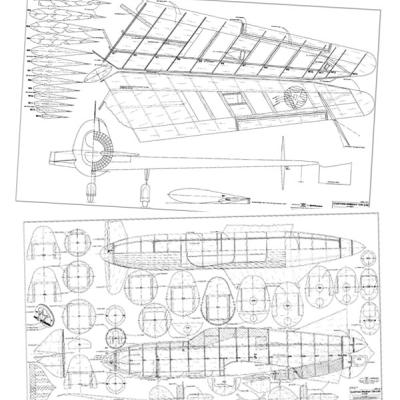
The CW-24B appealed to me, so I began searching for three-view drawings and other information for this airplane. I contacted modeler and aircraft designer Nick Ziroli who searched his collection of aircraft material and found three-views for the CW-24B.
In 1940, the U.S. Army held a design competition for a pusher-type fighter aircraft. The Curtiss-Wright Corporation submitted a canard named the XP-55 Ascender. Before committing to build the XP-55, the company created a full-scale test model, the CW-24B. It had a fabric-covered steel frame fuselage and a wooden wing, but the design needed many modifications.
In 1942, the U.S. Army ordered three XP-55s. They were built and tested, but after evaluating the aircraft’s performance, the Army did not see any advantage to the conventional designs, so the XP-55 never went into production.

The author’s completed Curtiss CW-24B is based on the U.S. Army’s full-scale test model. Only one full-scale CW-24B was built.
I drew the plans for the CW-24B, keeping the scale outline. I chose a symmetrical airfoil and gave the wingtips 5° of washout (I am not sure if the full-scale aircraft had any washout).
I calculated the location of the center of gravity (CG), but I must have been incorrect because on takeoff, the model leapt into the air and made a perfect loop—landing on all three wheels and bending the wire legs. I moved the motor battery forward to change the CG.
The model took off perfectly on the second attempt. I had positive control on all of the control surfaces. I was surprised by how much authority the tiny elevator had. The landing was perfect. I learned from those first few flights that CG location is critical.
Building the Wing
Cover the plans with clear plastic to protect them. The wing is built in two halves. Pin the bottom 1/4 x 1/8 spruce main spar to the building board over the plans. Position all of the ribs except F13 over the plans and glue them to the main spar. Insert and glue the top main spar to the ribs, and then the bottom rear spar to the ribs. Pin the washout guide strip to the building board as shown at the bottom of the plans on sheet 2.
Glue the bottom trailing edge (TE) sheeting to all of the ribs, and the 1/4 x 1/4 balsa spar to ribs W10 to W13. Glue on the top TE sheeting. Glue the sub-leading edge (LE) sheet to all the ribs and sand its edge so it follows the ribs’ contour.
Glue on the top LE sheeting. Apply adhesive to the balsa sheeting between ribs W1 and W4 and between the LE and the TE sheeting. Glue the balsa sheeting between ribs W10 and W13 as well. Glue the capstrips to the ribs.
Pull the extension wires for the aileron and the rudder servos. Flip the wing onto its back and sand the sub-LE on an angle so it follows the contour of the ribs. Apply adhesive to the LE sheeting, but be careful to not alter the washout.
Glue the hardwood blocks together for the landing gear. The landing gear blocks should have grooves in them to accept the landing gear wire. Glue in the aileron supports and the rudder servos. Glue the bottom sheeting over ribs W6, W7, and W10 to W13. Adhere the bottom capstrips.
Cut out the aileron from the wing. Glue the hinge spar and the side plates to the wing. Attach the plywood plate inside the aileron to hold the control horn. Glue the LE and side plates to the aileron, then finish-sand the wing.
Build the other half of the wing in the same manner then glue the two wing halves together. Smear adhesive onto the plywood brackets and slide them behind the main spars between ribs F2. Pin the dihedral shims under the W12 ribs. Apply adhesive to the W1 ribs and pin them to each other.
After it has set, remove the wing and glue in the hardwood block to ribs W1 and W2 to hold the wing bolts. Glue the plywood plate to ribs W1 and the LE sheeting to support the hardwood dowel. Insert and squirt adhesive in the hardwood dowel. Glue on the bottom sheeting between the W4 ribs to enclose the bottom of the wing.
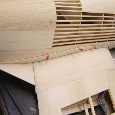
The 1/32-inch plywood doublers are glued to the fuselage sides.
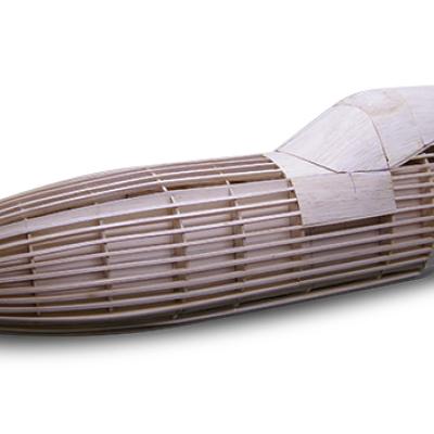
Here you can see the planking on the bottom of the rear section of the fuselage.
Building the Canard
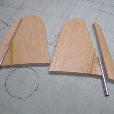
Cut a 1/4-inch outside diameter carbon-fiber tube to 91/4 inches long. Cut out the shape of the canard surfaces from 3/4-inch balsa sheet. On the hinge line, cut each canard into two sections: front and rear. Make the channel in both of them accept the 1/4-inch inside diameter aluminium or 4-inch-long brass tubes.
Slide the brass tubes onto the carbon-fiber tube so that the ends are flush. Pin the rear section of the canards to the building board. Temporarily insert the tubes into the grooves to ensure that they align. If satisfied, remove them and apply epoxy to the outside tubes. The canard surfaces must be able to be removed from the carbon-fiber tube.
Use epoxy to attach the front section of the canard to the rear one and to the carbon-fiber tubes. Drill a 1/16-inch hole through the middle of the tubes in the location shown on the plans. Sand each canard surface to the symmetrical airfoil.
Make the canard control arm using 1/32-inch steel sheeting. Drill a 1/4-inch and a 1/16-inch hole in the arm as shown on the plans. Solder it to the 1/4-inch wheel collar. Cut two brackets from 1/8-inch five-ply plywood to secure the canard to the fuselage.
Drill a 1/4-inch hole in each bracket and slide them onto the carbon-fiber tube and glue them to the F3 former, making sure that the carbon-fiber tube is horizontal in relation to the wing. Glue the 1/2-inch triangular stock to each side of the bracket to give it more support.
Cut the nose cone from the balsa block and glue former F1 to it. Sand the nose block to follow the contour of the fuselage. Inside the nose block, make a cavity for the canard’s control arm to rotate.
Glue the two magnets to formers F1 and F2, and the 1/8-inch guide dowels to former F1. Cut the slots in F1 so that the nose block can slide over the carbon-fiber tube.
Assemble the canard by sliding the carbon-fiber tube into the bracket and the control arm. Slide the canard surfaces onto the carbon-fiber tube. Match the holes in the canards with the holes in the carbon-fiber tube. Screw in self-tapping screws from the bottom. Check the alignment of the canard surfaces, and when finished, remove the screws.
Fins and Rudders
Each wing fin and the rudder are made from two halves: left and right. Cut out the shapes from 1/16-inch balsa sheet. Use 1/4 x 3/16-inch balsa to make the four hinge spars, sanding them so that they taper from the middle to the tip. Glue these spars to the TE of the fins and to the LE of the rudders.
Glue the tapered ribs to the side sheets, and the plywood plate inside the rudder to support the control horn. Secure the left side to the right side of the fin. Do the same for the rudders. Sand the fins and rudders then glue the fins to the wing.
Making the Landing Gear
Bend the piano wire to shape as shown on the plans. The nose gear slides into the brass tubing that is attached to former F6 with the thread. Install the steering arm to the nose gear. Use an Allen screw so it is easier to affix the arm. Install the main gear to check the alignment. When satisfied, remove the landing gear and make and add the wheel pants.
The hardwood blocks for the landing gear are glued to the ribs. The blocks have grooves to accept the landing gear wire.
Finishing the Model
After completing the filling and sanding, cover the model with your favorite material. The full-scale airplane was yellow with red and white horizontal stripes and one blue vertical stripe on the rudders. The front of the cockpit had a black, antiglare, triangular stripe all the way to the nose.
Install the control surfaces, control horns, and the servos then connect them to the control surfaces. Check the operation of all of the control surfaces. Make sure that the canards are oriented at 5° positive with the elevator servo in neutral. Install the motor and the ESC. Place a 6S battery onto the battery floor. I secured the ESC and battery with Velcro.
Check the CG by flipping the model upside down and balancing it so that the CG is at the location shown on the plans. If needed, reposition the battery for proper balance.
Flying
The takeoffs are no different than on most conventional-shape models. In the air, the Curtiss CW-24B is stable in all axes. During your first flight, gain some altitude and explore the flight characteristics.
When you land the aircraft, let it sink on its own. Don’t try to slow it by raising the nose too high. The model often lands on all three wheels. A short flight video is available on YouTube (see the “Sources” list).
Good luck building and flying this unique model!
Specifications
Order Plans